Multiple Choice
The schematic diagram of Figure 2-6 is an example of how a PLC output module is connected to: 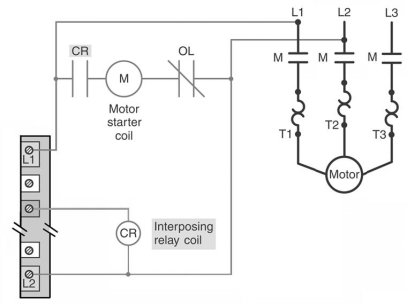
Interpret the results of standard costing reports and use this information for managerial decision-making.
Recognize the limitations and challenges of implementing a standard costing system.
Understand the concepts of standard costing, including standard quantities, rates, and cost variance analysis.
Calculate and interpret variances in direct materials, direct labor, and manufacturing overhead.
Definitions:
Related Questions
Q5: The on-delay timer (TON)starts timing when the
Q7: Promoting the rights of the poor,improving employment
Q8: All digital computing devices operate using the
Q8: Among the challenges facing those who practice
Q10: Block No.1 of the PLC block diagram
Q11: Assume output SOL C is energized at
Q29: Assume that a NC limit switch is
Q48: The instruction set for a particular PLC
Q49: The following information is available for a
Q56: At the start of the PLC scan