Short Answer
For the circuit shown in the figure,the ideal battery has an emf ε = 80 V.The four resistors have resistances of and Calculate the rate at which thermal energy is being generated in the resistor R4. 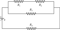
Definitions:
Related Questions
Q2: Suppose that the Department of Energy develops
Q18: At point P the <span
Q40: A wire carrying a current is
Q50: Two electrons are <span class="ql-formula"
Q63: A nuclear power plant has an
Q66: A point on the string of a
Q70: A negatively charged particle -Q is moving
Q127: An electric dipole consists of charges
Q196: When there is electric current through an
Q225: A 4.0-Ω resistor is connected to a