For the circuit shown in the figure, the ideal battery has an emf ? = 80 V. The four resistors have resistances of and Calculate the rate at which heat is being generated in the resistor R4. 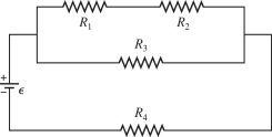
Definitions:
Work-In-Process
Inventory that includes materials that have been released for production but are not yet complete, representing a critical stage in manufacturing and costing processes.
Lateness
The measure of delay in a project, task, or delivery, indicating how much time has passed beyond the expected completion date.
Desktop Publishing
The process of using computer software to design and create publication documents, combining text and graphics.
Johnson's Rule
A scheduling method used to minimize the total time required to complete a group of jobs on two machines or workstations.
Q12: For the circuit shown in the figure,
Q29: If a calculated quantity has units
Q42: Two tiny particles having charges of +7.00
Q44: A single-turn loop of wire, having a
Q49: The length of a certain wire is
Q71: When a thin copper wire that is
Q73: A capacitor C is connected in series
Q83: What is the angular magnification of a
Q87: A15-Ω resistor is connected in parallel with
Q120: For the graph shown in the figure,